Process of 3D Scanning
In this Blog article, Reverse Engineering Service experts Mako GmbH provides an introduction to 3D Scanning and it’s process. 3D scanning is the process of analyzing a real-world object or environment to collect data on its shape and possibly its appearance.
Introduction to 3D Scanning
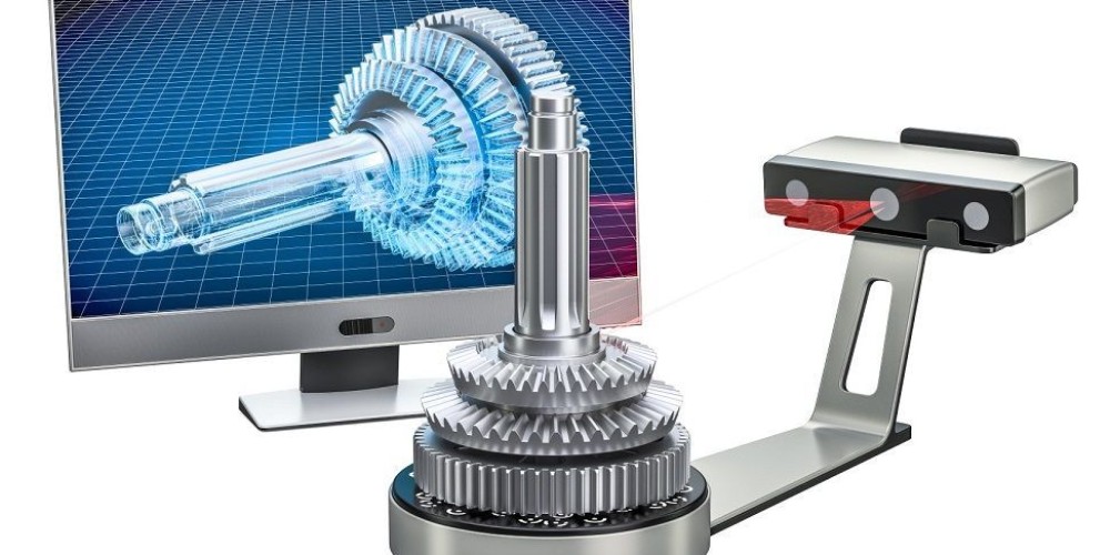
3D Laser Scanning is a non-contact, non-destructive technology that digitally captures the shape of physical objects using a line of laser light. 3D laser scanners create “point clouds” of data from the surface of an object. In other words, 3D laser scanning is a way to capture a physical object’s exact size and shape into the computer world as a digital 3-dimensional representation.
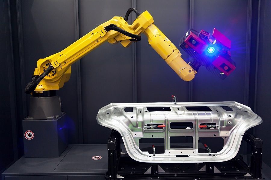
Combined 3D scanner and robotic arm automate scanning. Optical 3D coordinate measuring machine.
3D laser scanners measure fine details and capture free-form shapes to quickly generate highly accurate point clouds. 3D laser scanning is ideally suited to the measurement and inspection of contoured surfaces and complex geometries which require massive amounts of data for their accurate description and where doing this is impractical with the use of traditional measurement methods or a touch probe.
The 3D Scanning Process
- Data Acquisition via 3D Laser Scanning
In the first step of the 3D Laser Scanning process an object that is to be laser scanned is placed on the bed of the digitizer. Specialized software drives the laser probe above the surface of the object. The laser probe projects a line of laser light onto the surface while 2 sensor cameras continuously record the changing distance and shape of the laser line in three dimensions (XYZ) as it sweeps along the object.
- Resulting Data
The shape of the object appears as millions of points called a “point cloud” on the computer monitor as the laser moves around capturing the entire surface shape of the object. The process is very fast, gathering up to 750,000 points per second and very precise (to ±.0005″).
- Modeling Choice Depends on Application
After the huge point cloud data files are created, they are registered and merged into one three-dimensional representation of the object and post-processed with various software packages suitable for a specific application.
- Point Cloud Data for Inspection
If the data is to be used for inspection, the scanned object can be compared to the designer’s CAD nominal data. The result of this comparison process is delivered in the form of a “color map deviation report,” in PDF format, which pictorially describes the differences between the scan data and the CAD data.
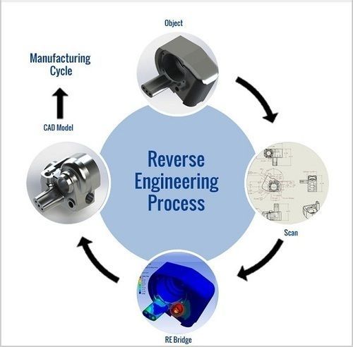
- CAD Model for Reverse Engineering
Final step is preparing the CAD Model for Reverse Engineering. Laser scanning is the fastest, most accurate, and automated way to acquire 3D digital data for Reverse Engineering. Again, using specialized software, the point cloud data is used to create a 3D CAD model of the part’s geometry. The CAD model enables the precise reproduction of the scanned object, or the object can be modified in the CAD model to correct imperfections. Laser Design can provide a surface model or the more complex solid model, whichever results are needed for the application.
If you want to explore more about Reverse Engineering, CAD software and how to master them check out our Blog Posts here or contact us here to get in touch with a Reverse Engineering expert!